




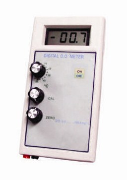
3 1/2 Digit LED display with salinity cell and other accessories (Table Model)
Author: admin
DIGITAL TO ANALOG (D/A) CONVERTOR USING R-2R NETWORK – GUPTA BRAND 200389
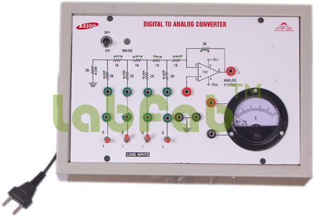
Objective : To study Digital to Analog convertor using R-2R network.
Features : Instrument comprises of DC Regulated Power Supply 5VDC/150mA, ±15VDC/150mA, 1 Voltmeter, 4 SPDT switches provided for selecting logic ‘1’ & logic ‘0’, one output indicators, Circuit diagram printed on the front panel
DIGITAL TO ANALOG (D/A) CONVERTOR USING WEIGHTED REGISTER NETWORK – GUPTA BRAND 200390
Objective : To study Digital to Analog convertor using Weighted Register network.
Features : Instrument comprises of DC Regulated Power Supply 5VDC/150mA, 15VDC/150mA, 1 Voltmeter, 4 SPDT switches provided for selecting logic ‘1’ & logic ‘0’, one output indicators, Circuit diagram for weighted resistor network & inverting circuit using IC 741 printed on the front panel
DIGITAL TRAINER TO VERIFY HALF ADDER & FULL ADDER – GUPTA BRAND 200380
No Description
DIGITAL TRINER TO STUDY & VERIFY TRUTH TABLES OF FLIP FLOPS USING TTL ICS AND NAND GATES – GUPTA BRAND 200382
Objective : To study & verify Truth tables of ‘RS’, ‘D’ Type, Flip Flops using NAND Gates & ‘D’, ‘T’ & ‘JK’ flip flops using TTL IC’s.
Features : Instrument comprises of DC Regulated Power Supply 5VDC/150mA, 4 logic inputs, logic ‘1’ & logic ‘0’ selectable using SPDT switches, 1Hz monoshot clock pulse, two output indicators, Circuit diagram for ‘RS’, ‘D’, ‘T’ & ‘JK’ & ‘JK Master slave’ flipflops are printed, their respective IC’s placed inside the cabinet & connections brought out on the sockets. 1
NOT gate for converting ‘RS’ flip-flops to ‘D’ type flipflop
DIGITAL TRINER TO VERIFY ADDERS & SUBTRACTORS USING NAND GATES – GUPTA BRAND 200381

Objective :To verify the truth table of Digital Half Adder, Half Subtractor, Full Adder & Full subtractor using NAND gates.
Features :Instrument comprises of DC Regulated Power Supply 5VDC/150mA for logic inputs, 3 SPDT switches provided for selecting logic ‘1’ & logic ‘0’, 3 NOT gates for providing compliments of the logic inputs, 2 Red LED output indicator, circuit diagram printed for 5 three input ‘NAND’ gates, 3 two input ‘NAND’ gates & 1 four inputs ‘NAND’ gates & their respective IC’s placed inside the cabinet & connections brought out at sockets.